

One of the parameters I wanted to integrate into the data logging system was speed.
Speed feels like one of the simplest signals you can measure. It’s just how fast you’re moving, right? On the surface, it sounds trivial: count wheel rotations, do some math, and you’re done.
As it turns out, speed sensing is one of those subsystems that looks simple only because OEM systems have already solved it extremely well.
How motorcycles normally measure speed
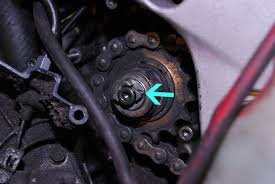
I first became curious about speed sensing when I was working on my clutch cable.
To access it, I had to remove the front sprocket cover on the engine side. Inside, I noticed a metallic ring with evenly spaced teeth, and a sensor positioned very close to it without touching.
Most motorcycles measure speed using:
- a toothed tone ring (or reluctor ring)
- a Hall-effect or variable reluctance sensor
As the ring rotates, each tooth passing the sensor generates a pulse. The ECU counts these pulses over time and converts them into wheel speed. That speed is then used for:
- the dashboard speed display
- traction control
- ABS
- wheel slip detection
My initial plan: count wheel rotations
My idea was straightforward:
- detect each wheel rotation
- count pulses
- use basic geometry to compute speed
In theory:
- wheel circumference = (2\pi r)
- rotations per second → speed
That part wasn’t wrong.
What I underestimated was how hard it is to get clean, reliable pulses on a real motorcycle.
First attempt: IR reflection sensing (and why it failed)
My first approach didn’t even use a Hall-effect sensor.
Instead, I tried an optical method:
- attach a reflective strip to the rear wheel
- shine light toward it
- detect the reflection with an IR sensor
I didn’t have an IR LED at the time, so I used a white LED instead (which does emit some infrared).
On the bench, it worked.
At low speed, rolling the bike slowly, it worked.
But once the bike was moving fast—especially above ~120–160 km/h—the system completely fell apart.
Symptoms included:
- wildly high speed readings
- random zero values
- unstable pulse timing
Daylight made it even worse. Sunlight floods the sensor with infrared radiation, completely overwhelming the signal.
This approach simply wasn’t viable outside a controlled environment.
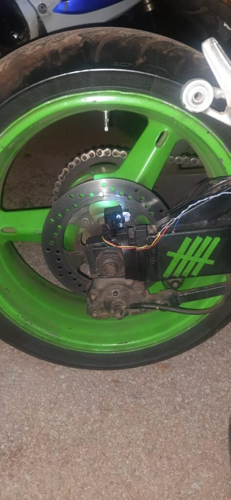
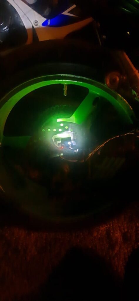
Second attempt: Hall-effect sensor and magnet
After abandoning optical sensing, I switched to a Hall-effect sensor, which is much closer to how OEM systems work.
The setup was:
- a small magnet attached to the rear wheel
- a Hall-effect sensor fixed near the wheel
- each pass of the magnet generated a pulse
Bench tests worked.
Slow-speed tests worked.
Rolling the bike by hand worked.
But once again, under real riding conditions, the readings became unreliable at higher speeds.
Why the Hall-effect setup still struggled
At first glance, this didn’t make sense.
A microcontroller can easily process signals faster than a wheel can spin, so why was the data still wrong?
Several issues were likely at play:
1. Sensor limitations
Not all Hall-effect sensors are designed for:
- high-frequency pulse detection
- vibration-heavy environments
- automotive EMI conditions
I was pushing a cheap sensor far outside its comfort zone.
2. Mechanical vibration
At speed, vibration introduces:
- signal jitter
- timing instability
- false triggering
Even slight movement of the sensor or magnet can cause extra pulses.
3. Electrical noise
Motorcycles are electrically noisy environments:
- ignition systems
- charging systems
- long wire runs
Without proper shielding and filtering, noise easily couples into digital inputs.
The software side is harder than “count pulses”
Another misconception I had was thinking that speed calculation was just geometry.
In reality, the software needs to:
- debounce pulses
- reject impossible timing values
- smooth sudden spikes
- handle missed pulses gracefully
If you don’t do this, you get:
- momentary speed jumps
- sudden drops to zero
- unstable readings
OEM systems spend a lot of effort making sure speed data is trustworthy, not just mathematically correct.
Why OEM speed sensing works so well
This experiment gave me a new appreciation for automotive sensors.
OEM speed sensors:
- are designed for extreme vibration
- tolerate heat and moisture
- use precise tone rings
- are calibrated for specific wheel speeds
- include robust signal conditioning
They need to work nearly 100% of the time, because incorrect speed data can break:
- traction control
- ABS logic
- stability systems
Something as simple as speed becomes a safety-critical signal.
Accepting reality: using GPS for speed
After multiple attempts with IR and Hall-effect sensing, I had to accept that my setup wasn’t reliable enough.
So I fell back to GPS-based speed.
GPS speed has drawbacks:
- slow update rate
- lag during acceleration
- poor accuracy at very low speeds
It wasn’t perfect, but it was consistent.
Lessons Learnt
Trying to measure speed taught me more than I expected.
I learned that:
- “simple” signals often aren’t simple
- sensors must be matched to their environment
- signal conditioning is just as important as hardware
- OEM systems earn their reliability
Most importantly, it showed how much engineering hides behind things we take completely for granted.
My Conclusion
Even though I didn’t match OEM performance, this wasn’t a failure.
It exposed:
- mechanical challenges
- electrical noise issues
- software filtering requirements
And it reinforced the idea that building reliable systems is very different from building prototypes.